5G Mobile Technology: Architecture, Devices, and Design Engineering

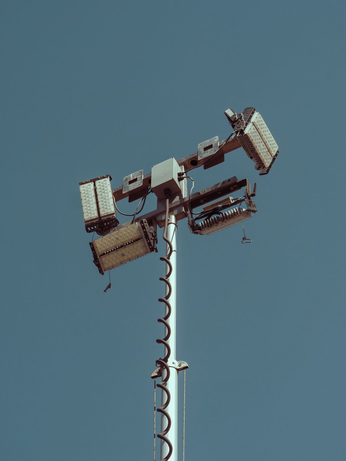
Figure 1: 5G transforms mobile networks from pure connectivity pipes into programmable, edge-intelligent platforms spanning sub-6 GHz and millimeter-wave spectrum.
---
1. Introduction: Why 5G Is a Paradigm Shift, Not Just Faster 4G
Fifth-generation mobile technology (5G) is rarely misunderstood as merely a faster version of 4G LTE. The leap from LTE to 5G New Radio (NR) is closer to the leap from dial-up to broadband: it introduces a new air interface, new spectrum regimes, new network architectures, and an entirely new service model. 5G was designed around three official use case families defined by the ITU-R IMT-2020 framework: enhanced Mobile Broadband (eMBB), Ultra-Reliable Low-Latency Communications (URLLC), and massive Machine-Type Communications (mMTC). These translate into three engineering targets: peak data rates of 20 Gbps, user-plane latency of 1 ms, and connection density of 1 million devices per square kilometer.
These targets cannot be achieved by spectrum efficiency improvements alone. They require a coordinated redesign of the radio access network (RAN), the core network, the transport layer, and the device ecosystem. This article examines the architecture, device engineering, and design principles that make 5G possible, with practical formulas and design trade-offs that engineers and product managers must understand.
---
2. The 5G Air Interface: New Radio (NR) Fundamentals
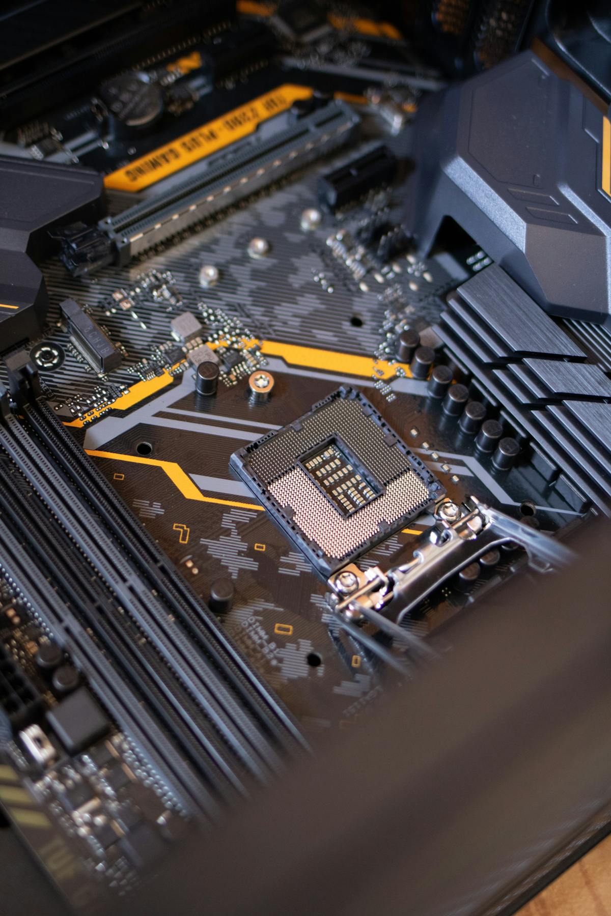
Figure 2: 5G NR spans sub-6 GHz for coverage and mmWave for capacity, each demanding distinct beamforming and antenna strategies.
2.1 Frequency Range 1 (FR1) and Frequency Range 2 (FR2)
3GPP Release 15 defines two frequency ranges for 5G NR. FR1 operates from 410 MHz to 7.125 GHz, including re-farmed 4G bands and new 5G-specific bands such as n77, n78, n79, and n28. FR2 operates from 24.25 GHz to 52.6 GHz, commonly referred to as millimeter-wave (mmWave) spectrum. The two ranges are not alternatives; they are complementary layers. FR1 provides coverage, mobility, and penetration, while FR2 provides capacity hotspots in dense urban venues, stadiums, factories, and private campuses.
Channel bandwidths differ dramatically. In FR1, carriers scale from 5 MHz to 100 MHz, with the most common deployments using 100 MHz contiguous channels in the 3.5 GHz band. In FR2, channel bandwidths range from 50 MHz to 400 MHz. Wider channels are essential to the multi-gigabit experience, but they come with higher path loss and shorter cell radii.
2.2 Orthogonal Frequency Division Multiplexing Enhancements
5G NR continues to use Orthogonal Frequency Division Multiplexing (OFDM), but with a more flexible numerology. Subcarrier spacing (SCS) in 4G LTE is fixed at 15 kHz. 5G NR supports multiple subcarrier spacings (15, 30, 60, 120, 240, 480 kHz), selected per frequency range and service type. Higher subcarrier spacings reduce symbol duration, which is necessary to maintain timing precision at mmWave frequencies and to support low-latency slots.
The Shannon-Hartley theorem remains the theoretical ceiling for any of these configurations:
$$C = B \cdot \log_2(1 + SNR)$$
Where $C$ is the channel capacity in bits per second, $B$ is the channel bandwidth in Hz, and $SNR$ is the signal-to-noise ratio. This formula explains why 5G pursues both wider bandwidth (larger $B$) and higher spectral efficiency (which increases effective $SNR$ through beamforming and MIMO). Doubling bandwidth doubles capacity, but increasing SNR from 0 dB to 10 dB increases capacity by a factor of approximately 3.5.
2.3 Massive MIMO and Beamforming
Massive MIMO is the defining physical-layer technology of mid-band 5G. In commercial networks, gNodeB antennas commonly employ 64 transmit and receive elements arranged as 64T64R arrays. The array gain and spatial multiplexing gain allow the base station to serve multiple users in the same time-frequency resource by forming directional beams.
The beamforming gain for an antenna array with $N$ elements is approximately:
$$G_{beam} \approx 10 \cdot \log_{10}(N)$$
A 64-element array therefore provides roughly 18 dB of additional gain. This gain is critical for compensating the higher propagation loss at 3.5 GHz compared to legacy 700–900 MHz 4G networks. In mmWave FR2, antenna arrays are even larger — typically 256 to 1,024 elements per panel — because path loss increases with the square of frequency and because mmWave signals do not penetrate walls or foliage effectively.
The Free-Space Path Loss (FSPL) equation quantifies this challenge:
$$FSPL = 20 \cdot \log_{10}(d) + 20 \cdot \log_{10}(f) + 20 \cdot \log_{10}\left(\frac{4\pi}{c}\right)$$
Where $d$ is distance in meters and $f$ is frequency in Hz. At 28 GHz, FSPL is approximately 22 dB higher than at 2.1 GHz for the same distance. This is why mmWave deployments require dense small-cell grids, beam tracking, and reflective surfaces rather than relying on outdoor-to-indoor penetration.
---
3. Network Architecture: From Core to Edge

Figure 3: 5G Core separates control and user planes and enables network slicing at the edge.
3.1 Service-Based Architecture (SBA)
5G Core introduces a Service-Based Architecture (SBA) in which network functions (NFs) expose services through well-defined APIs over HTTP/2. Unlike the 4G Evolved Packet Core (EPC), where network elements were tightly coupled through point-to-point interfaces, the 5G Core functions (AMF, SMF, UPF, PCF, AUSF, NRF, NEF, UDM, AF) are loosely coupled microservices. This decoupling enables operators to scale the user plane independently of the control plane, which is essential for high-throughput applications like 4K video and AR/VR.
The User Plane Function (UPF) is the most critical node for low latency. It can be deployed at the regional data center, the metro edge, or the local enterprise edge. The one-way latency budget from user device to application server is:
$$T_{total} = T_{air} + T_{fronthaul} + T_{midhaul} + T_{backhaul} + T_{core} + T_{server}$$
For URLLC, the target is $T_{total} \leq 1$ ms. This is only feasible if the UPF and application server are positioned at the edge, close to the radio. Mid-haul and backhaul transport must be fiber-based with deterministic scheduling, because every 100 km of fiber adds approximately 0.5 ms of round-trip propagation delay.
3.2 Network Slicing
Network slicing allows a single physical 5G infrastructure to be partitioned into multiple logical networks, each optimized for a service class. An operator can create an eMBB slice for consumers, a URLLC slice for industrial automation, and an mMTC slice for sensor telemetry. Slices are isolated in terms of bandwidth, latency, reliability, and security, but they share the same physical RAN and core infrastructure.
The slice resource allocation can be modeled as:
$$R_{slice} = R_{total} \cdot \alpha_i$$
Where $R_{total}$ is the total available radio resource and $\alpha_i$ is the guaranteed minimum resource ratio for slice $i$. Each slice has its own QoS policy, defined by a 5G QoS Identifier (5QI). For example, 5QI 1 is used for conversational voice, 5QI 2 for live streaming, and 5QI 82 for deterministic low-latency industrial traffic.
3.3 Open RAN and Disaggregation
Open RAN disaggregates the base station into three functional units: the Radio Unit (RU), the Distributed Unit (DU), and the Centralized Unit (CU). The RU performs radio frequency functions, the DU handles real-time Layer 1 and some Layer 2 functions, and the CU manages higher-layer protocol stack functions and interfaces to the core. This split enables operators to mix vendors, deploy software-defined radios on commodity hardware, and centralize baseband processing in edge data centers.
The functional splits introduce strict fronthaul latency requirements. The 7-2x split places most PHY functions in the DU and requires fronthaul latency below 100 microseconds and synchronization accuracy below 65 nanoseconds. These requirements are typically satisfied by eCPRI over dark fiber or active optical fronthaul.
---
4. Device Engineering: Smartphones, Modules, and CPE

Figure 4: 5G device engineering must balance antenna count, thermal budget, battery life, and global band support.
4.1 RF Front-End Design
A 5G smartphone RF front-end is one of the most complex consumer electronics assemblies. It must support more than 50 frequency bands, multiple carrier aggregation combinations, and both FR1 and FR2 operation. The front-end typically includes power amplifiers (PAs), low-noise amplifiers (LNAs), switches, duplexers, multiplexers, and antenna-tuning circuits. For mmWave, the RF front-end integrates phased arrays directly behind the antenna modules, with beam-management firmware controlling beam direction and beamwidth in real time.
Transmit power efficiency remains a challenge. PA efficiency in sub-6 GHz is typically 35–45%, while mmWave PA efficiency is 15–25%. The rest of the DC power is dissipated as heat. For a 23 dBm (200 mW) mmWave transmit burst, a 20% efficient PA draws 1 W of battery power. Because mmWave coverage is intermittent, the device frequently searches, switches, and re-transmits, increasing average power consumption.
4.2 Antenna Design and Beam Management
Smartphones integrate 4 to 8 sub-6 GHz antennas and 2 to 4 mmWave antenna modules. Sub-6 GHz antennas are typically PIFA (Planar Inverted-F Antenna) or slot antennas placed around the frame. mmWave antennas are arrays of patch antennas integrated into compact modules positioned at the corners of the device to maximize the probability that at least one module has a non-blocked path to the base station.
Beam management is a continuous procedure. The device measures reference signals transmitted by the gNodeB, selects the best transmit and receive beams, and reports beam quality to the network. If the user rotates the device or covers an antenna with a hand, the device must switch to an alternative beam within milliseconds to avoid session drops. This requires antenna diversity, rapid beam sweeping, and robust link adaptation.
4.3 Modem and Baseband
Commercial 5G modems integrate the baseband processor, RF transceiver, and power management. Modern flagship modems are manufactured on 4 nm process technology and support downlink carrier aggregation of up to 300 MHz in FR1 plus multiple 400 MHz mmWave carriers. Modem firmware handles dual connectivity (EN-DC / NE-DC), mobility between LTE and 5G, power-saving modes, and network slicing signaling.
The modem design trade-off is between capability and power. A high-end 5G modem can consume 1.2–1.8 W during active download. Device designers therefore implement discontinuous reception (DRX) cycles and idle-mode 5G anchoring to LTE where high throughput is not needed. For IoT devices and sensors, 5G RedCap (Reduced Capability) and NB-IoT over 5G provide lower-complexity, lower-power alternatives to full 5G NR.
---
5. Link Budget and Coverage Design
A 5G network design starts with a link budget that accounts for transmit power, antenna gains, feeder losses, body loss, penetration loss, and the receiver sensitivity target. The received power is:
$$P_{rx} = P_{tx} + G_{tx} + G_{rx} - L_{path} - L_{penetration} - L_{body} - L_{feeder}$$
For a typical mid-band 5G macro cell, $P_{tx}$ is 46 dBm (40 W) per sector, $G_{tx}$ from a 64T64R antenna is 21 dBi, and $G_{rx}$ for a smartphone is 0 dBi. Urban path loss at 3.5 GHz for 500 m can be modeled with a path loss exponent of 3.5:
$$L_{path} \approx 32.4 + 20\log_{10}(f) + 10 \cdot n \cdot \log_{10}(d)$$
Where $f$ is in MHz, $d$ is in km, and $n$ is the path loss exponent. For $f=3500$ MHz and $d=0.5$ km with $n=3.5$:
$$L_{path} \approx 32.4 + 70.9 + 17.5 \cdot 3.5 = 32.4 + 70.9 + 61.25 = 164.6 \text{ dB}$$
The available received power becomes:
$$P_{rx} = 46 + 21 + 0 - 164.6 - 8 - 0 - 3 = -108.6 \text{ dBm}$$
For 64-QAM modulation requiring an SNR of approximately 18 dB and a noise floor of -96 dBm in a 100 MHz channel, the link margin at 500 m is marginal. This confirms why mid-band 5G requires dense site grids or small cells for consistent indoor coverage, and why beamforming gain is essential to close the link budget.
---
6. Design Trade-Offs and Real-World Deployment
6.1 Coverage vs. Capacity
The coverage-versus-capacity trade-off drives 5G network planning. Macro sites on sub-6 GHz provide broad coverage at moderate capacity. Small cells on mmWave provide very high capacity in limited footprints. The optimal design is a heterogeneous network (HetNet) in which macro cells provide continuous service and small cells provide capacity in hot zones.
Capacity planning for a 5G cell follows:
$$C_{cell} = N_{users} \cdot \frac{R_{cell}}{N_{active}} \cdot \eta$$
Where $R_{cell}$ is the peak cell throughput, $N_{active}$ is the number of active users in the same time-frequency resources, and $\eta$ is a sector efficiency factor. In a mmWave small cell with 1 Gbps peak throughput and 50 active users, the average user rate is approximately 20 Mbps, assuming fair scheduling.
6.2 Latency-Sensitive Design
URLLC design requires more than low air latency. It requires deterministic networking. The 3GPP specification targets 0.5 ms radio latency for self-contained subframe structures and Mini-Slot scheduling. To reach end-to-end 1 ms latency, the UPF and application function must be co-located at the Multi-Access Edge Computing (MEC) node. Transport must support Time-Sensitive Networking (TSN) or Deterministic Networking (DetNet) for backhaul between the MEC and the radio.
Reliability targets for URLLC are 99.999% for a 32-byte packet within 1 ms. This requires packet duplication, multi-connectivity, and redundancy in both the radio and transport paths. Devices may be simultaneously connected to two gNodeBs transmitting the same packet, so the receiver has two independent chances to decode successfully.
6.3 Private 5G Networks
Private 5G is one of the fastest-growing deployment models for enterprises, factories, ports, mining, and healthcare. A private network can be deployed as a fully isolated local network, a shared public-private network, or a network slice on a public operator network. Local spectrum licenses (for example, CBRS in the United States at 3.55–3.7 GHz and local 5G licenses in Germany at 3.7–3.8 GHz) allow enterprises to operate their own 5G radio access without a mobile operator.
Designing a private 5G network requires a site survey, propagation modeling, capacity modeling, and interference analysis. For an indoor factory, the dominant propagation model changes from free-space to dominant reflector or ray-tracing because metal machinery, racks, and conveyor systems create multipath and blockage. Industrial automation networks also require precise time synchronization, typically IEEE 1588v2 PTP, to coordinate robots and PLCs.
---
7. Security and Resilience Design
5G introduces new security features but also new attack surfaces. The SBA exposes APIs between network functions, requiring mutual TLS, OAuth 2.0, and NF authentication. Edge computing places sensitive data and applications outside the operator's central data center, requiring zero-trust architecture at the edge. Network slicing isolation must be verified against side-channel attacks that could leak resources or timing information between slices.
Resilience design for 5G networks includes redundant transport paths, backup power for critical nodes, anti-jamming techniques for GNSS-synchronized networks, and physical security for street-level small cells. A single fiber cut to a DU cluster can disconnect hundreds of small cells, so transport topology design must include ring protection or dual-homing.
---
8. The Road Ahead: 5G-Advanced and 6G
Release 18 and beyond define 5G-Advanced, which adds AI/ML-driven network automation, enhanced XR support, sub-THz exploration, and further improvements in spectral efficiency. The transition from 5G to 6G will likely introduce native AI, integrated sensing and communication, and terahertz spectrum above 100 GHz. However, the fundamental design principles established in 5G — network slicing, edge intelligence, beamforming, and open disaggregated architectures — will remain the foundation for the next decade of mobile networks.
---
References: 3GPP TS 38.101, TS 38.104, TS 38.211; ITU-R M.2083-0 IMT-2020; O-RAN Alliance Architecture; IEEE 1588v2 PTP; NIST Private 5G/CBRS Guidelines; 3GPP Release 18 5G-Advanced.